
Page 2 - Troubleshooting Paper Mill Hydraulics Sample Excerpt 2
P. 2
No. 3 P.M. Winder Power Supply and Rider Roll
If the valve fails open, the pump will be de-stroked to a near 0 GPM
flow rate and the pressure at the outlet port will be very low. If the
valve fails closed, the pump will never compensate and will deliver
maximum flow at all times. With no relief valve in this system,
pressure will continue to build until a weak point in the system
ruptures or the electric motor kicks out. If either problem exists, turn
the pump off and make sure the pressure at the outlet port is 0 PSI.
Remove the compensator from the pump and take it apart. Inspect
the hollow orifices in the valve spool for contamination. Make sure
that there is no trash inside the compensator housing, Verify that the
spring is not bent, broken or rusted. Re-assemble the compensator
and attempt to reset the spring to the proper setting.
Oil that bypasses internally across the tight tolerances in the pump
will drain back to tank through the case drain to keep pressure from
building against the shaft seal. As the pump wears, these tolerances
become greater resulting in higher case flow. Thus case flow will
increase as the pump becomes more worn. The most effective way to
track pump wear is by measuring the amount of case flow. When
relatively new, case flow should be approximately 1 – 3%, or about
.47 – 1.4 GPM, of the total output. If case flow increases to as much
as 10% of the total pump volume, or about 4.7 GPM, the pump should
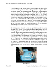
be replaced. The case drain line can be removed and ported into a
5-gallon bucket to check the flow rate. A flow meter has been installed
in the case drain line for convenient regular measurement of case
flow.
Page 32 No. 1 Pump
Troubleshooting Papermill Hydraulics