P.O. Box 689 Social Circle, GA 30025 678-267-3395 gpm@gpmhydraulic.com
|
July 2006
Do You Get This Newsletter Each Month In Your Email? If not, Click Here to Subscribe! |
||||||||||||
|
|||||||||||||
|
|
Maintenance Hydraulic Troubleshooting on Interactive CD Our nationally acclaimed
Maintenance Hydraulic Troubleshooting workshop
on six fully interactive CD's. Includes our MHT workshop manual.
6-CD Set - $1200 Individual CD's - $250
+ Shipping and Handling.
Click on http://gpmhydraulic.com/mhtcds.htm
to find out more.
|
||||||||||||
| 1. Stalls and Speed Reduction | |||||||||||||
 Al
Smiley - President, GPM Hydraulic Consulting, Inc. Al
Smiley - President, GPM Hydraulic Consulting, Inc. |
|||||||||||||
|
Temposonic Positioner Speed Problems
Q:
Our Edger board and saw positioners are moving too slow.
We have just changed the pump but still have the same problem.
Can you help us with this as we are getting “positioner alarms”
and it is slowing down production? -------Bill
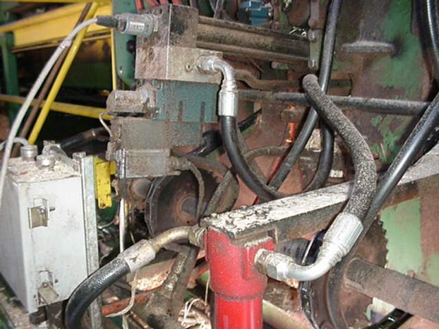
R. A: There are four Board Positoners (figure 1) on the Edger infeed table that position the board prior to feeding it into the two Edger Saws. If these positioners do not set to the desired position within a specific time period, a “positioner alarm” is indicated on the operator’s control screen. The Edger infeed table chain then has to be slowed down to continue operating.
Figure 1 Upon arriving at the plant
and surveying the system I located two accumulators in the system.
One accumulator supplied oil to the four Board positioners, the other
to the two Saw positioners. The
accumulators are used to supply oil at a high flow rate to the positioners
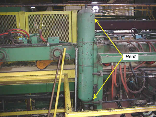
when required. The first test was to check the heat on the shells of the accumulators. When operating properly, the lower ½ or 2/3rds of the shell should be hotter than the top half. The friction of the oil in the shell causes this heat as the accumulator discharges and is refilled. The heat on the Saw positioners’ accumulator was 1050 all over the shell (Figure 2). This indicated that the bladder was being compressed too much as a result of the dry nitrogen pre-charge being too low.
Figure 2 The heat on the Board
Positioners accumulator was about ¾’s of the way up, again indicating an
undercharged condition. When
the plant went down for a shift change we installed a charging rig with a
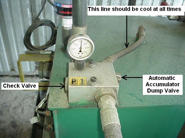
gauge to determine the nitrogen pre-charge. A block on the reservoir contained an automatic hydraulic dump valve (Figure 3). During normal operation the tank line of the valve should be cool. When the pump is turned off this valve will open dumping the pressurized hydraulic oil back to tank. When checking the dry nitrogen precharge, hydraulic pressure should be at 0 PSI.
Figure 3 As a safety note, the
hydraulic gauge should be checked to verify that the pressure has dropped to
0 prior to working on the machine. If
this is NOT done, severe injury or death can occur. With the charging rig and
gauge installed, 400 PSI was found in the Saw Positioners’ accumulator.
900 PSI was indicated when the Board Positioners’ accumulator was
checked. To determine the
proper precharge the maximum system pressure should be known.
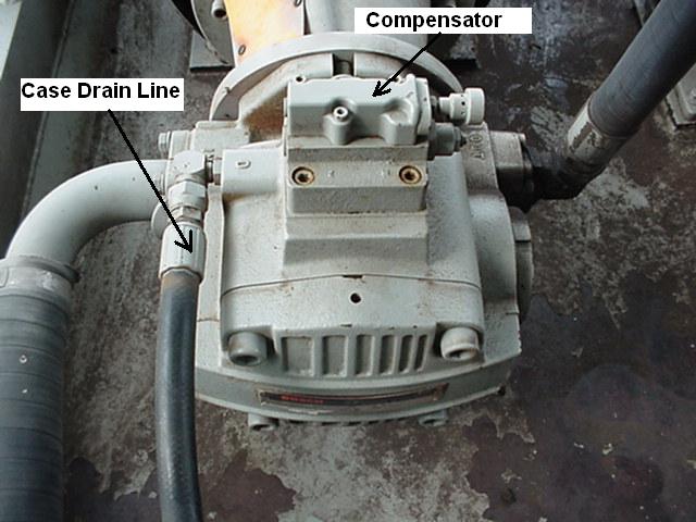
This is determined in this system by the pump compensator setting. The compensator (Figure 4) in this system was set to 2950 PSI; however the recommended setting was 2600 PSI. Accumulators that are used for volume should be pre-charged to ½ - 2/3rds the maximum system pressure. The proper precharge for these accumulators with a 2600 PSI compensator setting should be 1300 – 1716 PSI. We attempted to precharge each accumulator to 1300 PSI. Because of the low nitrogen in the existing bottles only 1200 PSI could be reached. The pump was then turned on and the compensator adjusted to 2600 PSI.
Figure 4 Upon checking with the
operator after the plant started back up he said there were no more position
alarms on the Edger. This also
allowed the infeed table speed to be increased, raising production levels.
I recommended that both accumulators be precharged to 1300 PSI when
the new nitrogen bottles were received. What occurred in this system
is typical of many circuits. The
pump was initially changed without any checks being made. Secondly, the pressure setting on the compensator, 2950 PSI,
was turned up to very near the maximum rating of the pump, 3000 PSI.
This high pressure increased the system heat, shock and electrical
amperage of the motor. Thirdly, the nitrogen precharge had not been set up to be
checked regularly. The
precharge on bladder accumulators should be checked twice a year.
Over a long period of time the nitrogen can seep through the rubber
bladder. If a speed problem
develops the precharge should be checked immediately. A preventative maintenance schedule should be set up for each hydraulic unit in the plant. This will improve the operating efficiency of the system and maximize production levels. |
|||||||||||||
| C.A. (Al) Smiley, Jr. founded "GPM" in october of 1994. Al initially worked with a leading hydraulic distributor from 1977 to 1986. Since 1987, he has taught and designed hydraulic troubleshooting programs for companies throughout the United States and Canada. Al does the technical writing for GPM's "Troubleshooting Manuals" He is certified and registered with the Fluid Power Society as a Fluid Power Specialist. He earned a Bachelor’s Degree in Education from the University of Mississippi in 1977. He writes columns for Hydraulics and Pneumatics, Southern Lumberman and Canadian Wood Products magazines on hydraulic troubleshooting methods. Al is married and has two boys. He is a musician and an avid golfer. | |||||||||||||
|
June was a busy month for us at GPM.
We’ve finally moved into our new office in Monroe, Georgia on
June 1st which is about 10 miles north of our old location in
Social Circle. We’ve had Al on the road teaching a Troubleshooting OSB Hydraulics workshop in Arcadia, Louisiana the first week of the month. The last week of the month he was at a papermill in Vicksburg, Mississippi teaching a Troubleshooting Winder and Woodyard Hydraulics course. In between, he taught a 1 day Troubleshooting Bosch Proportional Valves program near our office in Monroe, Georgia. He’s also been busy doing technical writing for upcoming customized troubleshooting courses. Obviously Al’s golf handicap went up in June but he did find some time to play with his band, Signal 22.
We sent Jack to Madera, California to teach a 4 day
Troubleshooting Corrugated Hydraulics program for a major paper and
packaging corporation. He
also taught our 3 day Maintenance Hydraulic Troubleshooting workshop here
in Monroe. Jack’s also
doing quite a bit of CAD drafting for future troubleshooting courses.
Between GPM and Jack’s RV Rental business he hasn’t had much time for
his favorite hobby, surfing on his laptop.
No rest for Alan either as he taught our 3 day,
Maintenance Hydraulic Troubleshooting course over a weekend at an
automotive brake pads manufacturer in LaGrange, Georgia.
He also worked with a papermill in South Carolina helping them
troubleshoot a hydraulic problem on their Roll Handling system. The last week in the month Alan was at Cordele, Georgia
teaching Troubleshooting OSB Hydraulics to 19 maintenance mechanics and
electricians. Alan did find
time to take a trip to the Georgia mountains with his wife on his
motorcycle in between his business travels.
This past month I’ve been developing the customized training manuals, filling orders for our interactive CD’s and getting our new office organized. Keeping up with these guys and my 8 year old daughter has kept me plenty busy. Thanks to everyone who helped make our month a success! Robin Garner Training Coordinator |
|||||||||||||
 Robin
Garner, GPM’s
Training Coordinator, joined the organization in 2004.
In addition to coordinating the training classes, she also does the
desktop publishing for GPM's troubleshooting manuals. Robin also manages
the marketing and accounting for the company. Robin
Garner, GPM’s
Training Coordinator, joined the organization in 2004.
In addition to coordinating the training classes, she also does the
desktop publishing for GPM's troubleshooting manuals. Robin also manages
the marketing and accounting for the company.
|
|||||||||||||
|
|
Hydraulic Schematic Symbols Explained This interactive CD is the fastest, easiest way available to learn hydraulic schematic symbols. Click here to order now! http://www.gpmhydraulic.com/gpmstore.htm $49.95 + Shipping & Handling
|
||||||||||||
|
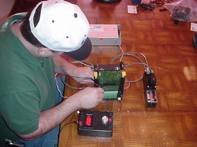
3. Proportional Valves Troubleshooting Tip. Proportional valves are many times
changed without any checks being made.
When the same problem exists, the original valve is rarely, if ever
re-installed back on the machine. Proportional valves are, in fact, one of
the easiest hydraulic components to troubleshoot. The first check that should be
made is that the power supply and enable signal are present at the
amplifier card. If an external card is used the multi-tester leads can be
placed on the specific terminals to check for these signals.
If the amplifier is mounted on the valve, the connecting cable can
be removed and the multi-tester leads placed in the specific pin holes to
check these voltages.
The next check that should be made
is the command signal from the machine controller.
This is usually a positive and negative D.C. volt signal with the
amplitude ranging from 0-10 volts. Some
valves operate off of a 0-12V or 0-24V input. In some cases the valve may
be operated by a 4-20 milliamp current signal.
This also can be checked at the valve amplifier if an external card
is used. If the valve has an
on board electronics (OBE) then the multi-tester leads can be inserted in
the appropriate pin holes on the connecting cable. Once you know that the command
voltage is available from the machine controller, you should determine if
the valve is a single or dual stage, hydraulic piloted valve.
If the valve is a single stage then the feedback voltage from the
LVDT can be checked to determine if the spool is shifting properly. This
can be checked at the external amp card or by connecting an inline test
box if the valve has on board electronics. The
LVDT feedback should follow the command signal.
For example, if a command voltage of positive 5 volts is selected,
then the LVDT should feedback a negative 5 volts signal.
If the LVDT follows the command signal then this means that the
valve is operating properly and shifting proportional to the command
signal. If the LVDT does not
follow the command signal then the valve spool may be stuck or the valve
may be out of null. Most
proportional valves have an electrical null on the amplifier card or a
mechanical null on the valve itself.
The valve coil may also be bad or the cable to the valve may be
loose or defective. The
continuity of the coil and cable can be checked with an ohm meter. On two stage valves, a pilot valve
is used to direct pilot pressure to shift the main valve spool.
Usually both the pilot and main valve spools contain an LVDT
feedback to indicate spool position.
The pilot valve LVDT should be checked as described above to verify
that it is operating properly. If the pilot valve is operating
properly, the feedback from the main spool LVDT should be checked.
The signal should also follow the command voltage. This can be
checked at the amplifier or with the test box for OBE valves. If there is no feedback at all then the main spool may be
stuck or the LVDT may be bad. On
many external valve amplifiers, a light will illuminate when the pilot or
main spool LVDT is bad. An
easy check to make is to replace the main spool LVDT with one from a new
valve.
|
|||||||||||||
|
If you've found our newsletter informative and beneficial please forward it to your co-workers and friends or click here to subscribe them to the newsletter. They will be automatically sent this newsletter each month when it is published for as long as they wish to continue receiving it. If for any reason a subscriber wishes to no longer receive the newsletter, a one-click link will remove them from our subscription list. |
|||||||||||||
|
|
Hydraulic Schematic Symbols Explained This interactive CD is the fastest, easiest way available to learn hydraulic schematic symbols.$49.95 + Shipping & Handling. Find out more, go to http://gpmhydraulic.com/symbolcd.htm
|
||||||||||||
|
Site Index [Home] [Our Training] [Hydraulic Consulting] [Our People] [Hydraulics Quiz] [Upcoming Events] [Contact Us] GPM Hydraulic Consulting, Inc. Box 1376 Monroe, GA 30655 (678)- 267-3395 |
|||||||||||||