P.O. Box 1376
Monroe, GA 30655
(770) 267-3787
gpm@gpmhydraulic.com
 |
 |
 |
 |
 |
 |
For an archive of past newsletters, please visit:
http://www.GPMHydraulic.com/newsletter_archive/
"Troubleshooting Hydraulics" Newsletter
www.gpmhydraulic.com
Click Here to view a brief video about our 3-day workshop
1. Proportional Valves- What You Can't See Can Cost You
2. Call GPM For Emergency Troubleshooting
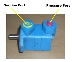
3. Why is the Suction Port Bigger than the Pressure Port?
4. Is It Time For A Hydraulic Reliability Assessment At Your Plant?
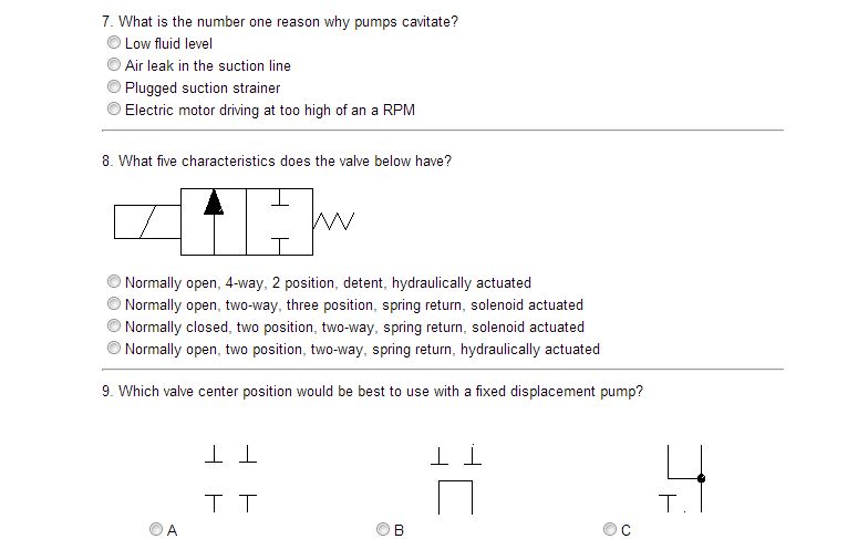
5. Take the Quiz!
6. 2013 Hands-On Public Reliability & Troubleshooting Workshops
After teaching a Troubleshooting Proportional Valves course recently a student told of a problem that occurred at his sawmill Ś a problem that ended up costing $96,000! He said that the bed lift cylinder on the Chip-N-Saw infeed had stopped operating. He then replaced the proportional valve with exactly the same part number as the original valve on the machine. When that didn't solve the problem several other components were changed in the system. He said, "If I would have known six months ago what I learned today, I could have saved my plant eight hours of downtime. The cost of our downtime is $12,000 per hour."
What he had learned that day was that on the proportional valve, the small threaded plugs had to be removed before installing the valve on the machine. The valve in question is known as a two-stage type valve (Figure 1). The valve requires both electrical power and hydraulic pilot pressure in order to operate. The purpose of the pilot valve (located on top) is to direct pilot pressure to the main valve spool. The pilot pressure can come from an internal passage inside the valve or from an external source.
Approximately 118PSI is required to overcome the springs in the valve housing to shift the main valve spool. In the schematic shown in Figure 2 notice that the pilot ptessure plug is located between the inlet line of the main valve and the pressure port of the pilot valve. When the plug is installed, pilot pressure must come from an external source and be supplied into the "X" port. Once the pilot valve spool is shifted into the straight arrows ("A" position) or crossed arrows ("B" position), oil will be directed to one end of the main valve spool. When valves are externally piloted a separate pump is many times used to supply the pilot fluid with a maximum pressure of approximately 200PSI. Another method is to use a pressure reducing valve connected from the main pump line to supply oil to the "X" port. By using a lower pressure to shift the spool, shock and wear on the valve is reduced.
In the cutaway shown in Figure 3, the pilot plug is located in an internal passage inside the main spool housing. If there is no pilot line connected to the "X" port then the main spool will not move when the pilot valve spool is shifted. This means that the valve must be converted from an externally to internally piloted valve. This is done by removing the pilot valve and removing the threaded plug. The plugs are usually metric so metric allen head wrenches will be required. Removing the plug hydraulically connects the oil at the "P" port of the main spool, through the valve body, to the "P" port of the pilot valve. The other plug found in the valve is in the drain line (Figure 4). When the pilot valve directs pilot pressure to one end of the main spool, the oil on the opposite side of the spool must be ported through the pilot valve and back to tank. When the pipe plug is installed, the drain flow is blocked to the "T" port passage of the main valve. Therefore, the oil must flow out of the "Y" port and back to tank.
In Figure 5, the location of the drain plug is shown inside the main spool housing. Valves are externally drained when high flow surges exist in the system return line. Any backpressure in the return line can affect the shifting of the main spool. If there is no line connected from the "Y" port of the valve back to the tank, then the main spool will not shift. To convert the valve from an external to an internal pilot, the drain line plug must be taken out. The pilot valve must be removed to access the drain plug (Figure 5). The oil that exhausts out of one end of the main spool can then flow through the pilot valve and back into the internal tank passage of the main spool.
With both plugs removed (Figure 6), the valve is configured for an internally piloted and drained valve. Most of these type proportional valves that are used in the industry are of this configuration. The OEM will remove the plugs before installing the valves in the system. In most cases, the part number is NOT changed. So, when the mechanic or electrician changes the valve, many times the plugs are not removed and the machine will not operate.
Another problem can occur when sending the original valve back for repair. When the valve is received at the repair shop, if the part number designates that the valve is externally pilot and drained, the pipe plugs are installed back in the valve. To prevent this from occurring, there are two options: First, order the valve with the part number that indicates the valve is internally piloted and drained (plugs removed). The second option is to make sure everyone in the maintenance department knows to remove the pipe plugs prior to installation. The first option is better.
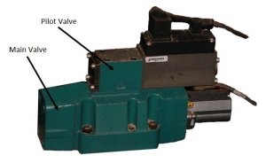 Figure 1 |
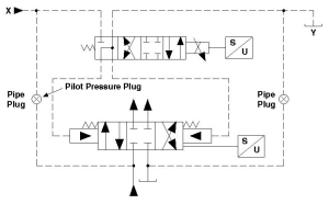 Figure 2 |
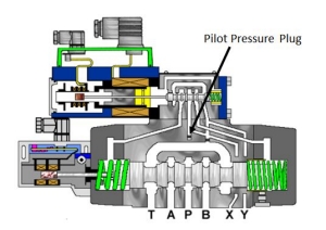 Figure 3 |
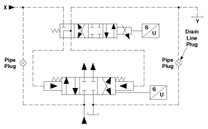 Figure 4 |
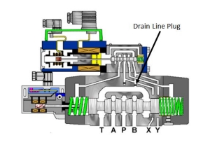 Figure 5 |
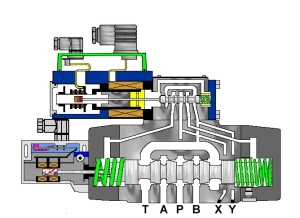 Figure 6 |

 |  |  |
Nothing is more expensive than unscheduled down time. GPMĺs customers know they can call whenever they have a troubleshooting issue they simply canĺt resolve. With over 75 years' experience dealing with hydraulic failures, our consultants have the resources to help troubleshoot whatever hydraulic problem you encounter. Whether youĺre experiencing a total system outage, repeated component failure or need a professionally designed hydraulic reliability assessment, the consultants at GPM can help. Call GPM for:
- In-plant Troubleshooting
- Leakage Problems
- Pressure Settings
- Shock Problems
- Hydraulic Reliability Assessments
- Hydraulic Troubleshooting Manual Development
- Startup Consulting and Recommendations
- Heat Problems
- Repeated Component Failures
- Speed Problems
Do you want to learn more about how GPM can help you? Go to http://gpmhydraulic.com/troubleshooting.php.
1/2 c. ketchup |