P.O. Box 689 Social Circle, GA 30025 770-464-0777 gpm@gpmhydraulic.com
|
February 2006
Do You Get This Newsletter Each Month In Your Email? If not, Click Here to Subscribe! |
||||||||||||
|
Click Here To Subscribe A Friend Or Coworker To Our Newsletter |
|||||||||||||
|
|||||||||||||
|
|
|||||||||||||
|
|
Maintenance Hydraulic Troubleshooting on Interactive CD Our nationally acclaimed
Maintenance Hydraulic Troubleshooting workshop
on six fully interactive CD's. Includes our MHT workshop manual.
6-CD Set - $1200 Individual CD's - $250
+ Shipping and Handling.
Click on http://gpmhydraulic.com/mhtcds.htm
to find out more.
|
||||||||||||
| 1. Leaks Costing You Money? | |||||||||||||
 Al
Smiley President GPM Hydraulic Consulting Inc. Al
Smiley President GPM Hydraulic Consulting Inc. |
|||||||||||||
|
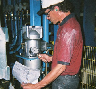
We have a lot of leaks on our hydraulic units, lines and valves. Is this common for most systems you have seen? We're unsure as to how much money this is costing us but we're looking for recommendations for improving our operation. Doug M. We've been asked to come in to many mills that have an excessive amount of leakage and make recommendations. On the other hand, I've seen seen several operations that have little or no leakage. There is no one answer as to why a system leaks. Oil leaks are expensive as a drop of oil that drips once per second can result in a loss of 405 gallons in one year! Leakage is usually caused by a poor installation, shock, improper maintenance and the local plant "knob turners'. Installation Piping, Hoses and Clamps When using pipe to plumb a hydraulic system schedule 80 and 160 should be used for the pressure lines and schedule 40 in the return and drain lines. Using schedule 40 pipe in the pressure line can result in leakage at the threads. When sealing the pipe threads a good hydraulic sealant should be used. Pipe dope and Teflon tape are not recommended simply because they are usually over applied. The sealant should be applied to the male fitting only starting 2 threads from the end. When sealant is over applied it ends up in the hydraulic system which causes leakage at O-rings, cylinder rod seals, as well as hydraulic pump and motor seals. The line from the pump to the valve manifold should not be piped rigid, particularly when closed center directional valves are used. Oil moves through a pressure line normally at 20 feet per second. The fluid speed may be higher or lower depending on the pipe size and system pressure. When the solenoid on a closed center directional valve is de-energized the oil flow from the pump is rapidly dead headed at the valve. Since oil is relatively non-compressible (1/2% per 1000 PSI) a pressure spike will occur. This spike can be 2 to 3 times the maximum operating pressure. A hose should be installed immediately down stream of the pump and also just prior to entering the valve manifold. The hoses will help absorb the pressure spike. You should never pipe rigid into a cylinder except in the case of a vertical or suspended load. If a velocity fuse is mounted at the cylinder port then a hose can be used. The velocity fuse will close if the hose ruptures preventing a free falling condition of the load. The length of the hose should normally not exceed 3 to 4 feet. The only exception to this rule is if the cylinder or motor is mounted to a movable carriage. During operation the length of the hose can change +2% to -6%. Hoses that are to long end up rubbing on another hose, a beam, and catwalk or on part of the machine (Figure 1). The initial system installation may have had the proper length but over several years the hose "magically" increases in length. This usually occurs because each time the maintenance person replaces the hose, he or she cuts it just a little longer!
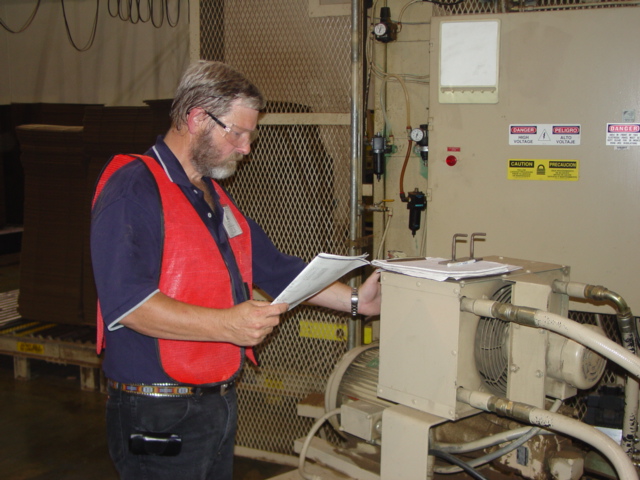
A hose that is too long will prematurely fail and cause a large loss of oil from the reservoir. To avoid a large loss of oil from the reservoir, the level switch should be set just below the lowest level the oil reaches when the cylinders are extended. If rubbing of the hose can not be avoided then a sleeve or protective cover should be installed. Many companies make sleeves that can usually be purchased by the reel. One of the main causes of leaks is improper clamping (Figure 2). many times the wrong type of clamp is used. Beam and conduit clamps are not designed to prevent the lines from moving when oil flow rapidly starts and stops in the line. A clamp made specifically for hydraulic pipe and tubing should be used and spaced approximately 5 feet. A clamp should also be installed within 6 inches of where the pipe or tube terminates. Materials used in the clamp may be Santoprene® (a thermoplastic elastomer), polypropylene or other types of UHMW (Ultra-High Molecular Weight) material. Clamps should be tightened periodically as the bolts that connect each half can vibrate loose over a period of time (Figure 3). To prevent the clamp base from loosening it should be welded to the beam as opposed to bolting it on.
Hydraulic pumps and motors many times leak at the shaft seals. Shaft seals in single direction pumps are usually rated at 10 PSI. The shaft seals in hydraulic motors that have external drain lines are generally rated for 25-50 PSI. The drain lines of pumps and motors should be run directly back to the tank and NOT in with the system return line. Filters and coolers are many times located in return lines and will create some back pressure as the oil returns to the reservoir. In addition, high flow surges in a return line can cause pressure to exceed the rating of the shaft seals. High Temperature Most all hydraulic systems are designed to operate at 120 degrees with a maximum temperature of a 140 degrees. High oil temperature causes a variety of problems within the system, one of those being leakage. O-rings tend to flatten out and can become pitted at high temperature and leak. Although the causes of heat in the hydraulic system are too numerous to mention here, the most common cause is improper pressure settings. When a hydraulic problem occurs, just about every knob in the system is turned. The first adjustment that is normally made is the adjustment on the pump, known as the compensator. If the adjustment is set above the system relief valve then the oil temperature can rise above 140 degrees causing o-ring failure as well as pump, motor and cylinder seal leakage.
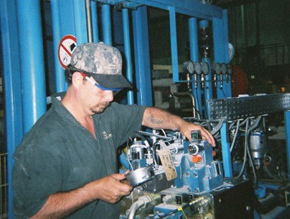
I recently consulted with a plant in Alabama that had heat and leakage problems on their debarker. The unit was running at 205 degrees! The system was leaking at the directional valve manifold (Figure 4) as well as the pump shaft and cylinder rod seals. We properly set the pressures in the system which reduced the temperature to 130 degrees several hours later. Unfortunately, the damage to the o-rings and seals had already been done. The plant had to replace the pump, cylinder and valve o-rings. Shock As mentioned previously hoses will absorb some of the shock that is generated in a hydraulic system. The other two devices that are normally used to reduce shock are relief valves and accumulators. The most common problem with relief valves is that the spring pressures are generally set to high. The system relief is usually located near the hydraulic pump and should be set 200 PSI above the maximum operating pressure if a fixed displacement pump is used. When using a relief valve with a pressure compensating pump a setting of 250 PSI above the compensator setting is appropriate. When properly set, the relief spool will momentarily open, dumping the pressurized fluid back to tank. Crossport relief valves are commonly found on hydraulic motor drives on cranes, knucklebooms, debarkers and conveyor drives, to name a few. These valves will momentarily open when the load starts moving and decelerate the load when stopping. When oil is initially ported to drive the load an initial pressure spike will occur. In the case of the debarker and planer feedrolls the spike is generated as the log and board are fed in. The crossport relief should be set to open when the pressure spike rises approximately 400 PSI above what is required to drive the maximum load. Improperly set crossports not only result in leakage at the fittings but can cause damage to the motor, machine and other system components. Accumulators are excellent devices for absorbing shock in hydraulic systems. Generally, bladder or diaphram types are used for absorbing shock. Threaded, in line shock suppressors that are pre-charged with dry nitrogen have also become popular within the last few years. When an accumulator is used to absorb shock three basic guide lines should be followed.
In Summary, anytime there is leakage in the system there is a reason for it. The entire system should be analyzed and the cause of the leaks identified. Several thousand dollars are wasted by companies each year in oil cost because leaks are excepted. Maintenance personnel should be educated on proper piping, clamping and hose installation procedures. Everyone in the plant should be instructed on the negative effects that random "kn turning" can have on the machine operation. Al Smiley |
|||||||||||||
| Al Smiley founded "GPM" in october of 1994. Al initially worked with a leading hydraulic distributor from 1977 to 1986. Since 1987, he has taught and designed hydraulic troubleshooting programs for companies throughout the United States and Canada. Al does the technical writing for GPM's "Troubleshooting Manuals" He is certified and registered with the Fluid Power Society as a Fluid Power Specialist. He earned a Bachelor’s Degree in Education from the University of Mississippi in 1977. He writes columns for Hydraulics and Pneumatics, Southern Lumberman and Canadian Wood Products magazines on hydraulic troubleshooting methods. | |||||||||||||
|
2. In-plant consulting and troubleshooting
Nothing is more expensive than unscheduled down time. GPM’s customers know they can call whenever they have a troubleshooting issue they simply can’t resolve. With over 50 years experience dealing with hydraulic failures, our consultants have the resources to help troubleshoot whatever hydraulic problem you encounter. Whether you’re experiencing a total system outage, repeated component failure or just need a professionally designed preventive maintenance schedule, the consultants at GPM can help. Call GPM for In-plant Troubleshooting Leakage Problems Pressure Settings Shock Problems Preventive
Maintenance Scheduling Hydraulic Troubleshooting Manual Development Startup
Consulting and Recommendations Heat
Problems Repeated
Component Failures Speed Problems Do you want to learn more on how GPM can help you? Go to http://gpmhydraulic.com/troubleshooting.htm
|
|||||||||||||
|
|
Troubleshooting Proportional Valves This is the same manual used in our Troubleshooting Proportional Valves public seminar in a fully searchable pdf format on CD. Learn how check the LVDT feedback, current, adjust the amplifier, null a valve, use a battery box and much much more. This eBook can be downloaded onto a network, control room computer, palm top, lap top, office computer or home computer for faster troubleshooting. Click here to order now! http://www.gpmhydraulic.com/gpmstore.htm $49.95 + Shipping & Handling
|
||||||||||||
|
New this month! Become a registered member of the GPM Forum. We want to build a global hydraulic topics community and we would like YOU to be a part of it. As a member you can discuss with us and other GPM Forum members problems concerning hydraulic pumps, heat problems, speed problems, shock, fluid maintenance, pressure settings or just share some of your ideas with other members. We are asking that members post job opportunities that they are aware of that concern hydraulics and valuable links to sources of hydraulic information. Registered members can reply to a thread, start a new thread, send and receive private messages to other users without revealing an email address, upload an avatar and ask to become a moderator. What are you waiting for? Register now, its free! www.gpmhydraulic.com/forum
|
|||||||||||||
|
If you've found our newsletter informative and beneficial please forward it to your co-workers and friends or click here to subscribe them to the newsletter. They will be automatically sent this newsletter each month when it is published for as long as they wish to continue receiving it. If for any reason a subscriber wishes to no longer receive the newsletter, a one-click link will remove them from our subscription list. |
|||||||||||||
|
|
Hydraulic Schematic Symbols Explained This interactive CD is the fastest, easiest way available to learn hydraulic schematic symbols.$49.95 + Shipping & Handling. Find out more, go to http://gpmhydraulic.com/symbolcd.htm
|
||||||||||||
|
Site Index [Home] [Our Training] [Hydraulic Consulting] [Our People] [Hydraulics Quiz] [Upcoming Events] [Contact Us] GPM Hydraulic Consulting, Inc. Box 1376 Monroe, GA 30655 (678) 267-3395 |
|||||||||||||